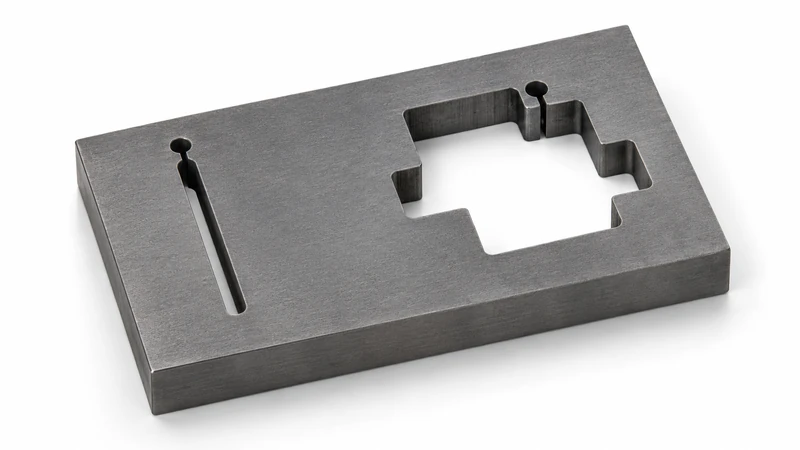
This precision insert was made from D2 tool steel hardened to approximately 58–60 HRC. The part measured about 65 × 40 × 12 mm and included a narrow slot of approximately 1.20 mm, an internal corner radius of about R0.15 mm, and critical profile tolerances in the ±0.01 mm range. Once the material had been hardened, small end mills would have been increasingly affected by cutter wear, rigidity, and tool-radius limits, so the critical through-profiles were produced by Wire EDM and finished with multiple skim cuts.
This case is based on our manufacturing experience with similar hardened tool-steel components. Customer identity, original drawings, and certain project-specific details are withheld or anonymized under confidentiality requirements.
Moving the Critical Profiles to Wire EDM After Hardening
The first decision in this project was the machining route. With the D2 already hardened to approximately 58–60 HRC, the narrow slot and small internal corners placed more demand on small rotating tools; cutter wear, rigidity, and the physical tool radius all affected how consistently the required profile could be produced.
The main through-features were therefore assigned to Wire EDM. This allowed the hardened material to be profiled without relying on a small cutting tool to carry the full machining load. The R0.15 mm internal corners were treated as controlled Wire EDM features rather than assumed to be mathematically sharp, with the actual corner condition governed by the wire, spark gap, and corner-control strategy described in Makino's Wire EDM technical guidance.
Separating the Rough Cut from the Skim Cuts
The first rough cut removed the main stock and established the profile for finishing. Multiple skim cuts were then used to refine the critical dimensions, slot width, and surface condition instead of relying on the first pass to produce the final ±0.01 mm profile, giving each finishing pass a defined dimensional and surface-control role.
The closed internal contour was provided with a start hole before Wire EDM so the wire could be threaded through the workpiece and begin the internal cut. Its location was coordinated with the cutting path and workholding and kept clear of the critical profile area.
Inspection Focused on the Finished Profile
After Wire EDM, inspection covered the approximately 1.20 mm slot, R0.15 mm internal corners, critical profile dimensions, parallelism, and the resulting surface condition. The ±0.01 mm and R0.15 mm values shown here are anonymized representative requirements for this type of project rather than default standards applied to every Wire EDM component, and final acceptance remains tied to the production drawing.
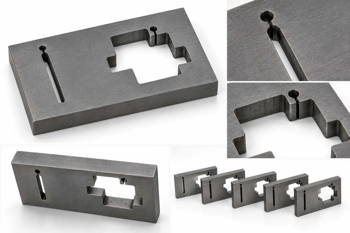
Surface condition also remained part of the review because EDM affects more than geometry. Research on AISI D2 tool steel has shown that EDM parameters influence recast-layer thickness and surface roughness, so higher-demand tooling parts may require closer attention to final skim conditions and any downstream finishing requirements.
Need a Precision Wire EDM Project Reviewed?
If your part includes narrow slots, small internal corners, closed internal profiles, precision through-profiles, or high-accuracy features that are difficult to produce consistently by conventional cutting, send the 3D model together with a 2D drawing showing the critical dimensions, tolerances, material condition, and surface requirements. Through our engineering support, we can review the Wire EDM route based on the actual geometry, including start-hole planning, rough cutting, skim cuts, and the corresponding inspection approach.
References & Sources
Source note: These references support the Wire EDM roughing and skim-cut strategy, corner accuracy, start-hole threading, and D2 surface-integrity principles discussed in this case. Project dimensions, tolerances, hardness, and specific process conditions are anonymized representative values from our experience with similar components. Final production requirements remain subject to the customer drawing and actual project conditions.
FAQ