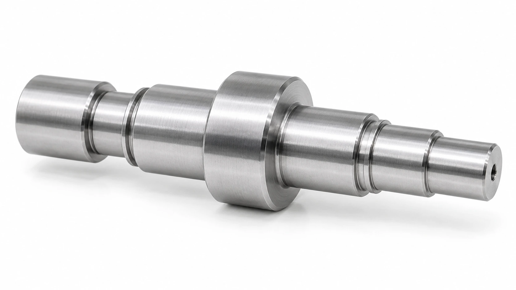
This project involved a 304 stainless steel precision shaft for automation equipment. The part was about Ø28 × 140 mm and included several functional journals, shoulders, and locating faces. A few critical journal diameters needed to be held within ±0.01 mm, but hitting those diameter tolerances alone was not enough to guarantee smooth rotation after assembly.
When bearings, couplings, or sensors are mounted on different journals, what matters is whether those journals still run on the same working axis and whether the locating faces stay square to that axis. A shaft can pass diameter checks and still show visible runout, uneven bearing loading, or poor coupling alignment once it is assembled.
Key Project Requirements
| Item |
Representative Requirement / Focus |
| Part |
Precision shaft for automation equipment |
| Material |
304 stainless steel |
| Approx. size |
Ø28 × 140 mm |
| Main process |
CNC turning + local finishing |
| Critical journal diameter tolerance |
±0.01 mm |
| Coaxial relationship between two functional journals |
0.02 mm (final GD&T callout per drawing) |
| Radial runout of critical journals |
≤0.02 mm to datum axis |
| Face runout of locating shoulder |
≤0.02 mm to datum axis |
| Critical journal surface finish |
Ra 0.8 μm |
| Machining focus |
Reduce re-chucking and keep critical journals on a consistent turning axis |
| Inspection focus |
Journal diameter, radial runout, face runout, and functional surface finish |
Note: These are representative requirements for this type of project. Final fits, tolerance classes, datum definitions, and runout limits are set by the customer drawing and actual assembly conditions.
The Critical Journals Were Treated as One Rotating System
Where possible, the main coaxial features were turned in one stable setup. This reduces the chance of shifting the rotational reference each time the part is re-chucked. For this type of part, the CNC turning plan has to consider the journals as a connected rotating system, not as a series of unrelated diameters.
If a second setup is required by the part geometry, an already-machined journal can be used as a locating reference, while the journals and locating faces that matter most to rotational performance are left for later finishing.
Threads, relief grooves, and shoulder radii also need to match the mating components. Around bearing, coupling, or sensor locations, these details can affect axial seating and final assembly even if the journal diameter itself is correct.
The representative critical-journal tolerance in this case was ±0.01 mm. If an actual drawing uses ISO fit classes, the journal may instead be specified with a fit such as h6 or h7, depending on the bearing or coupling requirement. SKF shaft-tolerance guidance is a useful reference for why shaft-seat tolerances vary with the bearing arrangement and operating condition. The drawing and mating condition still determine the final callout.
Diameter Was Only One Part of the Inspection
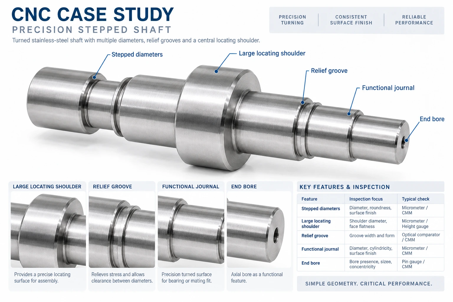
After turning, journal diameter is checked first, but it is not the only acceptance criterion for a multi-journal shaft. The critical journals also need to be checked against the same datum axis, using the inspection method appropriate to the drawing and tolerance. Our quality assurance process matches dimensional and geometric checks to the confirmed project requirements.
For this representative case, the radial runout target for the critical journals was ≤0.02 mm, with locating-face runout also controlled to ≤0.02 mm relative to the datum axis.
The representative requirements also included a 0.02 mm coaxial relationship between two functional journals. For a rotating shaft, radial runout and face runout are especially useful because they describe how the surfaces behave around the working axis. ASME Y14.5 provides the GD&T framework for datum references and runout controls; the exact feature control frame should follow the customer drawing.
The critical journal surfaces were finished to about Ra 0.8 μm where they actually served bearing, support, or other precision interfaces. Finishing strategy matters because insert geometry, feed, depth of cut, rigidity, and tool condition all affect the resulting surface. Sandvik Coromant turning guidance illustrates the relationship between finishing conditions and surface quality. Non-functional surfaces did not need the same finish.
The Final Check Is How the Shaft Runs in Assembly
For precision shafts used in automation equipment, tighter numbers everywhere do not automatically mean a better part. The useful controls are the ones tied to bearing fit, coupling alignment, and rotational stability.
Holding a journal to ±0.01 mm is only one part of the job. The final result also depends on runout between journals and how the shaft actually behaves once assembled.
Need a Similar Precision Shaft Reviewed?
If you are developing a shaft for bearings, couplings, sensors, or other automation assemblies, send us your 2D drawing, 3D model, material, quantity, and critical fit requirements. Tongyong Industries can provide engineering support to review the CNC turning route, workholding, journal fits, tolerance classes, runout requirements, and finishing strategy for critical surfaces.
Discuss Your Project
References & Sources
ASME — Y14.5-2018 (R2024) — Dimensioning and Tolerancing
SKF — Specifications for Shafts and Housing Support Surfaces
Sandvik Coromant — Turning Geometry — Finish, Medium & Rough
Source note: These references support the GD&T/runout, shaft-fit, and turning/surface-finish principles discussed in this case. Project-specific tolerances and acceptance criteria remain subject to the customer drawing and actual assembly conditions.
FAQ