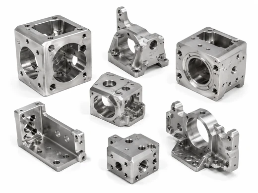
Multi-Face Housings & Brackets
Complex housings and brackets with holes, pockets and mounting faces positioned across multiple sides.
- Housings
- Brackets
- Mounting Bodies
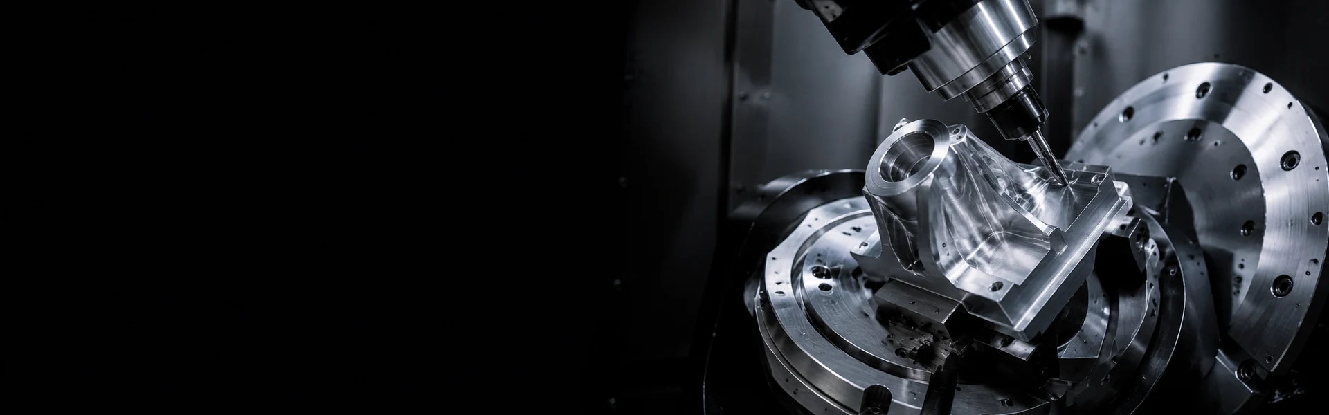
Part types
These are the parts where 5-axis pays off - features on many faces, free-form surfaces, or tolerances that can't survive being re-fixtured. Each type below is here for a specific reason.
Complex housings and brackets with holes, pockets and mounting faces positioned across multiple sides.
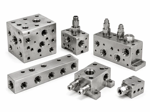
Angled ports, intersecting passages and sealing faces machined across multiple sides with fewer setups.
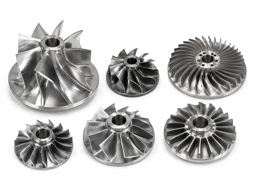
Contoured blades and curved surfaces machined with improved tool access to support consistent profiles.
Tolerance & inspection
The hard numbers procurement and engineering ask for - what we can hold, how we verify it, and how the part scales from one prototype to repeat production on the same fixtures and datums.
Why Tongyong
Complex, multi-face components machined with fewer setups to support dimensional consistency and efficient production.
An engineer checks tool access, wall thickness and tolerances against your model before quoting — and flags anything that will fight the process.
The complete program is simulated — tool, holder, fixture and part — so compound-angle moves are proven safe before a chip is cut.
Datums and fixturing are planned so the part is referenced once and true position holds across every face in the setup.
Why choose 5-axis
For complex, multi-face parts, 5-axis machining can reduce setups and improve access to angled and contoured features. Machining more features in fewer fixtures helps maintain positional relationships and reduce variation from re-clamping.

Features across multiple faces can be machined in fewer fixtures, helping maintain positional relationships and reduce variation from re-clamping.

Changing the tool-to-part angle improves access to angled bores, deep pockets and complex surfaces that may be difficult to reach with 3-axis machining.

Shorter tools and improved cutting angles can reduce deflection and chatter, helping produce smoother contoured surfaces with less secondary finishing.

Fewer re-clamping steps can reduce handling of thin walls and fine features, helping lower the risk of damage and improve process efficiency.
Metals we machine
| Preview | Material | Grades | Best for |
|---|---|---|---|
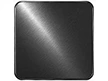 |
Carbon & Alloy Steel | 1045 · 4140 · 4340 | High strength and hardness for shafts, gears and structural components, with heat treatment or plating as required. |
 |
Brass | C360 · C260 · C272 | Conductive and decorative, with grades suited to machined connectors, valves and fittings. |
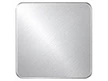 |
Aluminium | 6061 · 6063 · 7075 · 5052 · 2024 | Lightweight and corrosion-resistant, with grades suited to housings, brackets and structural components. |
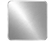 |
Stainless Steel | 303 · 304 · 316 · 17-4PH · 416 | Corrosion-resistant, strong and hygienic — for parts that must endure moisture, chemicals or sterilization without losing integrity. |
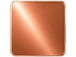 |
Copper | C101 · C110 | High electrical and thermal conductivity for bus bars, electrodes and thermal components. |
 |
Titanium | Grade 2 · Grade 5 | High strength-to-weight ratio and corrosion resistance for demanding lightweight components. |
Which approach fits
Both approaches use a 5-axis machine. The key difference is whether the rotary axes move during cutting—and the right choice depends on your part geometry, features and surface requirements.
| Aspect | Simultaneous 5-axis | 3+2 positional (5-sided) |
|---|---|---|
| How it works | All five axes move together during the cut, so the tool follows free-form paths continuously. | Rotary axes lock the part at a fixed angle, then 3-axis milling runs on that face. |
| Best for | Contoured, organic surfaces such as impellers, turbine blades, blends and sculpted forms. | Prismatic parts with features on several faces, such as housings, manifolds and brackets. |
| Tool reach | Shorter tools at optimal angles, with better rigidity and finish in deep or angled areas. | Strong, stable cuts per face; reach is limited to what each fixed angle exposes. |
| Cost & speed | Higher setup and programming effort, justified on complex one-piece geometry. | Economical multi-face machining with minimal re-fixturing; faster to quote. |
Not sure which fits? Send your STEP model - we'll recommend the approach that gives the accuracy you need at the lowest cost, and often combine both on one part.
From our blog
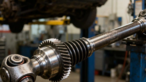
Why a single blanket tolerance is the wrong way to spec a part, and how confirming critical dimensions at DFM keeps quality high and cost sensible.
Common questions
Yes — aluminium, stainless steel and titanium are all machined regularly on our 5-axis centres, alongside carbon & alloy steel, brass and copper depending on your part's structural and corrosion-resistance requirements.
Choose 5-axis when a part has features on several faces, compound angles or free-form surfaces, or when tolerances between faces are too tight to survive re-fixturing. If every face can be reached from one locked angle, 3+2 positional is usually enough; for simple prismatic parts, 3-axis is the most economical. Send your model and we'll advise.
The 5-axis machine rate typically runs 50–100% higher than 3-axis. But for parts that need multiple setups on a 3-axis machine, the total part cost is often lower on 5-axis once you account for reduced setup time, less handling, and fewer tolerance stack-up issues from re-fixturing. We'll quote both approaches if your part could go either way, so you can compare total cost, not just the hourly rate.
Multi-face housings and brackets, angled manifolds and fluid bodies, and impellers or bladed parts with continuously curved surfaces are the parts where 5-axis pays off most — anywhere features span multiple faces or a tool path must stay tangent to a curved surface.
Linear and milled features typically hold from ±0.01mm, with true position across faces held in one setup — since the part is referenced once, position between faces beats the same part run across multiple 3-axis setups. Critical dimensions are verified on CNC CMM with documented inspection reports.
Yes — from a single prototype to validate design and fit, through to repeatable production runs on the same fixtures and datums, so process knowledge carries forward as volumes scale.
A 3D model (STEP / IGES / X_T) plus a 2D drawing for critical dimensions, tolerances, datums and finish. The 3D model is essential for 5-axis programming and collision simulation — a sketch is enough to start the conversation.
Send your STEP, IGES, or X_T model. Include a 2D drawing if critical tolerances, datums, or surface finishes are required. Our engineering team will review your 5-axis machining requirements, assess manufacturing feasibility, and provide quotation and DFM feedback based on your project.
We use cookies to collect information about how you use this site. We use this information to make the website work as well as possible and improve our services.more details