Introduction
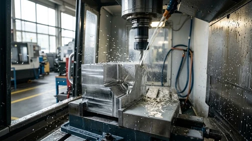
In precision manufacturing, many CNC machining costs are not caused by material selection or part size alone. Instead, certain design decisions can significantly increase machining time, tooling difficulty, setup requirements, and overall production risk.
When developing a product, adopting Design for Manufacturability (DFM) is a practical method to balance part function, manufacturing feasibility, and cost. This guide explores how specific geometric features translate into manufacturing challenges and provides practical strategies to optimize your design before production begins.
How Design Features Affect CNC Machining Cost
The relationship between a CAD model and the final invoice follows a direct path:
Design choice → Manufacturing difficulty → Cost and lead time.
Every feature on a technical drawing can impact the machining process in several ways:
- Tooling requirements: Complex geometries may require custom cutters or micro-tools, increasing tooling expenses and extending procurement times.
- Machining time: Features that cause tool vibration typically force programmers to reduce cutting speeds and feed rates, increasing machine cycle time.
- Setup complexity: Components requiring machining on multiple faces often need custom fixtures and repeated manual realignments.
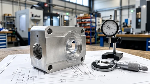
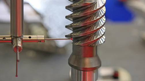
- Inspection considerations: Hard-to-reach internal features can complicate coordinate measuring machine (CMM) routines and increase quality control efforts.
Deep Pockets and Small Internal Radii
Deep cavities combined with small internal radii are among the most common cost drivers in CNC milling. Standard CNC milling tools cannot create mathematically sharp internal corners because cutting tools have a radius.
To clear small corners, machinists often need to use smaller tools with longer tool extensions. This reduces tool rigidity and increases the risk of vibration and tool deflection during the cut.
Manufacturing Perspective: Why This Happens in CNC Production
On the shop floor, the challenge is rarely just about whether a cutter can physically fit into a corner. The actual production concern is whether the tool can reach the feature while maintaining sufficient rigidity and stable cutting conditions. Machinists evaluate tool diameter, tool length, holder interference, and spindle nose clearance. If a pocket is too deep relative to the corner radius, the long-reach tool can chatter, resulting in poor surface finishes or broken end mills.
Design Solutions:
- Increase the internal radius to be slightly larger than the standard tool radius.
- Use corner relief (such as dog-bone or T-bone shapes) if a square mating component needs to fit inside.
- Redesign the geometry to reduce the overall depth of the pocket where possible.
Thin Walls and Flexible Features
Engineers often reduce wall thickness to save weight, but in manufacturing, machine positioning accuracy does not always equal final part accuracy. Cutting forces generated during machining can push against thin walls, causing them to flex or deform during CNC turning or milling. Additionally, material residual stresses and fixture influence can cause the part to warp once it is released from the machine.
Manufacturing Perspective: The Logic Behind Thin Wall Challenges
The difficulty of machining thin walls does not depend on wall thickness alone. It is also heavily influenced by the unsupported height of the wall, the overall feature size, the machining sequence, and the clamping method. A thin wall that is well-supported by surrounding bulk material during the roughing pass is much easier to manufacture than a freestanding thin rib.
Design Solutions:
- Avoid unnecessary thin walls if they do not contribute to the part's function.
- Add support features like ribs or gussets to increase structural stiffness.
- Consider the machining sequence and allow for thicker walls where possible to provide stability.
Deep Holes, Threads, and Difficult Internal Features
Deep holes and long internal threads present unique challenges related to tool accessibility, chip evacuation, and cooling. As a drill or tap goes deeper into the material, tool rigidity decreases, and clearing metal chips becomes increasingly difficult, which can lead to tool breakage.
Manufacturing Perspective: Engineering Judgment
Instead of applying fixed ratios, designers should evaluate the functional intent of the hole. Engineering judgment plays a critical role here. Designers should consider:
- Whether full-depth threads are functionally necessary (often, only the first few threads carry the majority of the load).
- Whether blind holes can be converted into through holes to aid chip evacuation.
- Whether the hole direction can be changed to align with other primary features, saving a setup.
- Whether special processing can be reduced by using standard thread sizes.
Undercuts and Features Requiring Special Tooling
Undercuts are recessed features that cannot be reached by a standard end mill cutting straight down. These features typically require special cutters (like T-slot or lollipop cutters), additional setups, or secondary operations like EDM (Electrical Discharge Machining).
Whenever possible, designers should use standard professional terminology such as local relief or corner relief, and utilize standard groove dimensions so the manufacturer can use off-the-shelf tooling rather than grinding custom cutters.
Multiple Setups and Machining Orientation
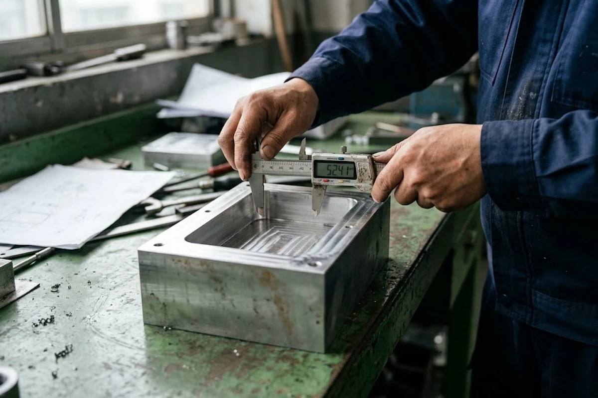
If a part has features on all six sides, it typically requires repeated setups. Each time a part is unclamped, flipped, and re-clamped, datum changes occur, which introduces tolerance stacking and increases fixture requirements.
Manufacturing Perspective: The Value of 5-Axis Machining
While 5-axis machining is often viewed as "more advanced," its true engineering value lies in the ability to reduce setups, maintain datum relationships across multiple faces, and improve tool accessibility. However, not every part benefits economically from 5-axis machining; simple prismatic parts may still be cheaper to run on 3-axis machines.
The most economical machining strategy is often the one that reduces unnecessary setups while maintaining functional accuracy.
Engineering Example: Redesigning a Deep Aluminum Housing for Easier CNC Machining
Original Design:
An initial design for an electronic housing featured a deep cavity, small internal radii (R1.0 mm at a depth of 40 mm), and multiple side features requiring access from four different angles.
Manufacturing Impact:
This geometry required smaller tools with long extensions to reach the bottom corners, leading to longer machining time. The side features also dictated additional setups, increasing the risk of alignment errors.
Design Optimization:
The engineering team decided to increase the internal radius to R3.5 mm, allowing a standard 6 mm tool to sweep the corners efficiently. They also improved tool accessibility by reducing the cavity depth where possible and simplified the machining orientation by moving two side ports to the top face.
Results:
The revised design allowed for easier machining and a more stable cutting process. By eliminating two setups and using standard rigid tooling, the overall manufacturing complexity was significantly lowered.
CNC Design Improvements Checklist
| Design Issue |
Manufacturing Impact |
Possible Improvement |
| Small internal radius |
Requires smaller tools and may increase vibration risk |
Increase radius or add corner relief |
| Deep pockets |
Longer tools reduce rigidity and machining stability |
Reduce depth or improve accessibility |
| Thin walls |
Cutting forces may cause deformation |
Add support or adjust machining sequence |
| Multiple setups |
Increases fixture and datum transfer complexity |
Simplify feature orientation |
CNC Design Review Checklist Before Production
Before you prepare your CAD files for quotation with CNCIVO or any manufacturing partner, review these key points:
- Are tools accessible for all milled features?
- Are internal corners practical for standard end mills?
- Are thin features sufficiently supported?
- Can setups be reduced by aligning features to fewer faces?
- Are critical dimensions clearly identified without over-tolerancing non-critical areas? To understand more about applying standard shop tolerances, review our specific tolerance guidelines.
References & Sources
- ASME Y14.5-2018 — Dimensioning and Tolerancing. American Society of Mechanical Engineers. Defines standard geometric dimensioning principles to avoid costly over-tolerancing.
- NIST Engineering Laboratory, National Institute of Standards and Technology. Provides foundational engineering data for manufacturing accuracy and applied industrial mechanics.
- Altintas, Y. (2012) — Manufacturing Automation: Metal Cutting Mechanics, Machine Tool Vibrations, and CNC Design. Cambridge University Press. Serves as a reference for metal cutting mechanics. (Note: Industry references are utilized to guide structure and standard nomenclature only.)
Ready to bring your optimized design to life? Explore our custom CNC machining capabilities and let TONGYONG’s engineering team support your next production run.
FAQ