Introduction
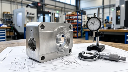
When mechanical engineers and procurement teams evaluate multiple quotes for identical 3D CAD models, quotation differences are often driven primarily by tolerance requirements, surface finishes, inspection protocols, and manufacturing assumptions. Even when raw material volumes remain identical, specified drawing tolerances dictate how a machine shop approaches setup planning, cutting parameters, and quality verification.
In precision manufacturing, tighter tolerances are frequently associated with superior quality, but higher precision is not always functionally necessary. The primary consideration is whether a specified tolerance level serves the component’s functional fit and operating life. Achieving tight limits is rarely as simple as commanding a machine tool to cut with higher precision; instead, it introduces compounding constraints related to workpiece rigidity, thermal behavior, tool wear, and inspection verification.
Understanding how tolerance definitions directly affect shop-floor operations enables engineering teams to design reliable components while avoiding unnecessary manufacturing complexity and inflated unit costs.
What Are CNC Machining Tolerances?
A CNC machining tolerance defines the acceptable boundary of dimensional variation between a designed nominal value and the final physical part. Because subtractive machining involves dynamic cutting forces, tool deflection, material properties, and thermal fluctuations, producing parts to an absolute, zero-deviation nominal dimension across an entire batch is physically impossible. Tolerances establish the operational window in which a manufactured part will fit, mate, and perform reliably.
It is important to differentiate between machine accuracy and machining tolerances:
- Machine Accuracy: The mechanical ability of a CNC machine tool's drive and positioning system to reach a specific coordinate.
- Machining Tolerance: The acceptable dimensional and geometric envelope specified by the designer on an engineering drawing.
To illustrate how a dimensional tolerance translates into manufacturing boundaries, consider a typical precision bore callout: Ø20.00 ± 0.01 mm.
| Parameter |
Engineering Value |
Manufacturing Interpretation |
| Nominal Dimension |
Ø 20.00 mm |
Theoretical design target defined in the 3D model and 2D drawing. |
| Upper Specification Limit (USL) |
20.01 mm |
Maximum material limit allowable for part acceptance. |
| Lower Specification Limit (LSL) |
19.99 mm |
Minimum material limit allowable for part acceptance. |
| Total Permissible Tolerance Zone |
0.02 mm (20 µm Band) |
The total process variation window available across tool wear, deflection, and temperature shifts. |
In physical production, this 0.02 mm total window indicates that standard roughing and single-pass finishing may not be sufficient. Depending on the feature requirements, material, and production method, additional finishing operations such as precision boring, reaming, or other controlled processes may be required. Furthermore, tool wear must be closely monitored, cutting temperatures must be managed to prevent dimensional drift, and verification cannot rely on standard hand tools alone.
Tolerances are specified not to quantify the difficulty of manufacturing, but to communicate functional necessity—distinguishing non-critical clearances from interference fits, bearing journals, and precision alignment surfaces.
Why Do Tighter CNC Machining Tolerances Increase Cost?
The relationship between dimensional tolerance and manufacturing cost is inherently non-linear. While standard commercial tolerances can typically be produced with conventional tooling and standard cycle times, tightening tolerance requirements significantly can increase manufacturing complexity and cost because additional process control and verification may be required.
| Tolerance Category |
Typical Range |
Cycle Time & Process Complexity |
Primary Cost Drivers |
| General Tolerances |
± 0.10 mm and above |
Baseline Cycle Time |
High-speed roughing and standard single-pass finishing.Standard tooling; conventional feeds; floor-level sampling inspection; minimal scrap risk. |
| Precision Tolerances |
± 0.02 mm to ± 0.01 mm |
Moderate Increase |
Requires multi-pass finishing and conservative feeds.Tool wear compensation; frequent tool offsets; dedicated plug/bore gauges or scheduled CMM verification. |
| Controlled Limits |
Sub-0.01 mm (< ± 0.01 mm) |
Elevated Overhead |
Significantly extended spindle and stabilization cycles.Specialized boring, reaming, or grinding operations; strict thermal stabilization; 100% CMM lab inspection. |
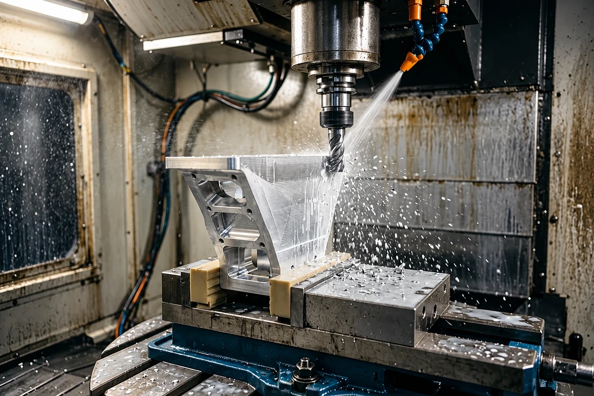
This non-linear cost curve is driven by accumulated demands across process control, fixturing strategies, and quality inspection.
1. Process Control and Tooling Dynamics
As acceptable tolerance bands narrow, machine shops must actively control physical factors that have negligible impact during commercial-grade machining:
- Tool Deflection and Cutting Parameters: Cutting tools naturally deflect under lateral forces. To maintain tight dimensions, machinists must reduce depth of cut and feed rates, often adding light spring passes to remove minimal stock left by tool deflection, which extends overall spindle cycle time.
- Tool Wear Monitoring: Cutting edges degrade continuously due to abrasive and thermal wear. While standard tolerances can accommodate normal flank wear over a longer production run, tighter limits require frequent tool offset adjustments and earlier tool replacement to prevent parts from drifting out of specification.
- Thermal Expansion: Workpiece materials expand and contract with temperature changes. For example, aluminum alloys exhibit noticeable thermal expansion even under moderate ambient shifts. If cutting heat builds up in the part, dimensions measured immediately after machining can fall outside specification once the component cools to room temperature.
- Material Stress Relief: Removing significant material from rolled plates or extruded stock releases internal residual stresses, which can cause thin walls or asymmetrical geometries to distort after unclamping.
2. Fixturing and Multi-Setup Strategy
Complex parts often require operations across multiple faces, demanding careful consideration of workholding and reference points:
- Setup Variations: Small variations can accumulate during repeated setups due to fixture conditions, locating methods, and datum transfer. When features machined in separate setups must maintain tight positional relationships, specialized fixtures or multi-axis machining configurations are often necessary to finish critical features in a single clamping.
- Clamping Distortion: Thin-walled components can deform elastically under mechanical vise pressure. If a part is machined flat while clamped under excessive force, it will relax and warp once released, making it difficult to hold tight dimensional or planar requirements without custom fixturing.
3. Inspection Requirements and Verification Overhead
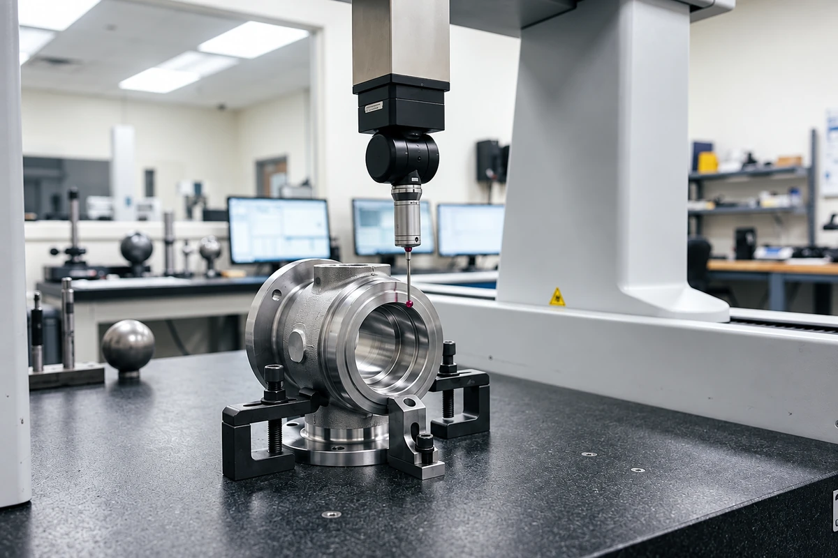
A key principle of manufacturing metrology is the 10:1 Gage Maker’s Rule: measurement instruments must be at least 10 times more precise than the tolerance being evaluated, with a 4:1 ratio accepted as a minimum in modern industrial practice.
When tolerances become restrictive, simple hand tools are often inadequate for demonstrating conformance. In practical CNC production, inspection requirements can become a significant part of the overall production effort for tight tolerance components. Parts may need to stabilize in a temperature-controlled metrology environment before measurement, and complex geometric features require dedicated Coordinate Measuring Machine (CMM) programming and formal reporting.
Internal Reference: To understand how inspection workflows and metrology equipment ensure dimensional compliance, explore our complete guide to CNC inspection and quality control.
Typical CNC Machining Tolerance Levels
In engineering design, tolerances should be assigned according to feature functionality rather than blanket assumptions. The following ranges are common engineering considerations rather than universal manufacturing limits, as actual achievable tolerances depend on part geometry, material selection, machining processes, tooling stability, and inspection methods.
| Tolerance Range |
General Application |
Typical Manufacturing Considerations |
| ± 0.10 mm to ± 0.05 mm |
General machined features and non-critical dimensions |
Standard CNC milling and turning setups; conventional carbide tooling; efficient feed rates and standard cycle times. |
| ± 0.02 mm to ± 0.01 mm |
Precision fits and functional features (bearing bores, dowel locations, sliding fits) |
Multi-pass finishing; dedicated tooling such as precision reamers or boring operations; controlled cutting parameters and dedicated inspection. |
| Below ± 0.01 mm |
Applications requiring specialized process control and verification |
Precision finishing methods; temperature-stabilized environments; rigid fixturing; comprehensive CMM or specialized metrology verification. |
Why Not Every Dimension Needs Tight Tolerances
A frequent design issue encountered on manufacturing drawings is the blanket tolerance applied uniformly across all dimensions in a CAD title block. If an engineering drawing specifies a tight global tolerance across every feature, non-functional chamfers, clearance pockets, and cosmetic outer surfaces are subjected to the same manufacturing restrictions as critical mating interfaces.
A practical Design for Manufacturability (DFM) approach applies functional tolerance allocation:
- Bearing Bores and Journals: Require tailored tolerances to maintain predictable press or transition fits without excessive mechanical stress.
- Locating Pin Holes: Require tight center-to-center relationships to ensure accurate alignment during assembly.
- Sealing Surfaces: Depend primarily on flatness and surface finish rather than strict absolute thickness tolerances to maintain gasket compression.
- Clearance Holes and Non-Mating Profiles: Can accept broader general tolerances, enabling rapid roughing and lowering cycle times without risking assembly performance.
How GD&T Helps Improve CNC Manufacturability
Traditional coordinate dimensioning often relies on independent plus-minus linear tolerances for feature locations, creating a square tolerance zone. For example, when locating a bolt hole with ±0.05 mm in both X and Y directions, parts with slight deviations along one axis may be rejected even if the mating bolt would pass through without interference.
Geometric Dimensioning and Tolerancing (GD&T), defined by standards such as ASME Y14.5, communicates functional engineering intent more effectively:
- Position Tolerance: Provides a more practical tolerance zone for controlling hole patterns while maintaining assembly requirements. Because mating pins and bolts are circular, a cylindrical tolerance zone reflects functional assembly clearance far better than linear bounds.
- Maximum Material Condition (MMC): When applied to clearance holes, MMC permits additional positional variation as the hole size approaches its upper limit, reducing unnecessary rejections without compromising mechanical assembly.
- Functional Datum Reference Frames: Explicit datums clarify which surfaces serve as locating references, aligning machine shop workholding strategies directly with functional inspection setups.
Common Tolerance Design Mistakes
Common DFM reviews often identify several tolerance-related issues that unnecessarily increase manufacturing complexity:
- Applying Tight Tolerances to Every Dimension Using automated CAD drawing templates to apply a single tight tolerance across the entire part forces the manufacturer to treat non-critical features as precision operations, inflating cycle times and driving unnecessary scrap risk.
- Ignoring the Functional Purpose of Dimensions Specifying tight limits without evaluating how mating components interact can create conflicting dimensional constraints and tolerance stack-up issues, complicating fixturing without improving performance.
- Defining Tolerances Without Considering Inspection Methods Specifying extremely tight geometric or dimensional callouts on flexible thin-walled geometries or inside deep, narrow cavities where physical measurement probes cannot reach creates significant verification challenges on the production floor.
How Engineers Can Reduce CNC Machining Costs Through Better Tolerance Design
Engineering teams can optimize manufacturing feasibility and production budgets by incorporating four practical design practices:
- Identify Critical Features Early: Separate dimensions into critical functional interfaces versus secondary clearance geometry, applying precision callouts only where strictly required for fit, alignment, or sealing.
- Use Appropriate General Tolerance Standards: Use appropriate general tolerance standards, such as ISO 2768 when applicable, based on project requirements, allowing title-block standards to govern non-critical geometry.
- Establish Logical Functional Datums: Base datum reference frames on real mating surfaces rather than arbitrary theoretical features, simplifying workholding setups and CMM alignment.
- Discuss Requirements During DFM Review: Review 2D drawings with your manufacturing partner prior to production to clarify tolerance intent, resolve difficult inspection scenarios, and identify cost-saving adjustments.
Internal Reference: To verify that your technical drawings, step files, and tolerance notes are structured for efficient manufacturing review, refer to our CNC machining RFQ checklist.
Conclusion
CNC machining tolerances should reflect actual functional requirements rather than arbitrary precision goals. When tolerances exceed what is standard for a given geometry and material, manufacturing complexity rises through specialized tooling requirements, continuous process monitoring, custom workholding, and comprehensive metrology verification.
By utilizing functional tolerancing, establishing clear datums through GD&T, and engaging in early DFM discussions, engineering teams can maintain product performance and assembly integrity while ensuring cost-effective, repeatable production.
References & Sources
FAQ