CNC Milling
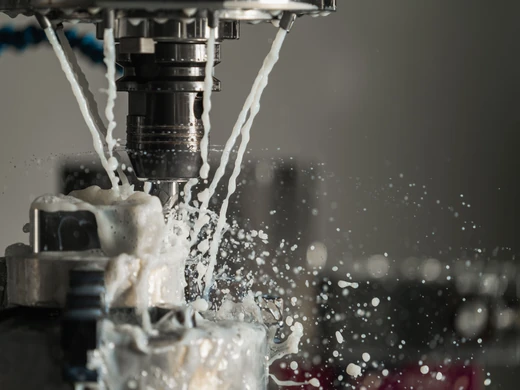
Prismatic parts, brackets, plates and housings milled from billet or plate with tight repeatability across batches.
What is CNC machining?
CNC machining is a subtractive manufacturing process: cutting tools remove material from solid billet or bar under computer control, following the geometry in your CAD model, following the geometry in your CAD model. It supports tight tolerances, consistent repeatability and a wide choice of metals, without the dedicated mould or die costs typically associated with moulding or casting.
Because parts are machined directly from solid stock, CNC is well suited to prototypes, validation parts and low-to-mid-volume production where accuracy and material integrity are important.
Prismatic parts, brackets, plates and housings milled from billet or plate with tight repeatability across batches.
Round and shaft parts turned on CNC lathes, with live tooling for cross-holes, flats and slots in one setup.
Complex geometry, compound angles and contoured surfaces machined in fewer setups for better accuracy.
CNC micromachining produces tiny precision parts with micro cutters for medical and electronic components at micron tolerance.
Sharp internal corners, hardened tool steel and fine detail features cut by electrical discharge.
Coordinate anodizing, polishing, bead blasting and other finishing processes to achieve the required appearance, texture and surface performance.
Why Tongyong
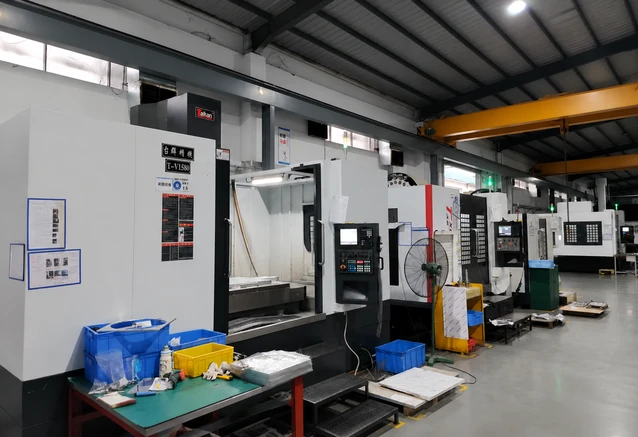
You communicate directly with our engineering team throughout the project. We provide DFM feedback, material and process advice, and practical suggestions to improve manufacturability. Our team then coordinates machining, finishing, inspection and documentation through one project workflow.
With manufacturing experience since 2003 and a broad range of machining capabilities, we reduce supplier hand-offs and support your part from initial prototype to repeatable production with consistent engineering coordination.
Multi-axis machining can reduce the number of setups and re-fixturing operations, helping improve positional consistency and reduce unnecessary handling.
Before machining begins, our engineers review your drawing for manufacturability, material suitability and tolerance feasibility, helping identify potential issues early.
Critical dimensions and tolerances are reviewed and agreed against your drawing, then measured and documented according to the confirmed inspection requirements.
We machine a broad range of aluminium, stainless steel, alloy steel, brass, copper, titanium and specialty alloys, selected to suit the drawing and application.
From initial validation parts to repeatable production runs, we carry forward the approved process requirements and manufacturing knowledge as volumes scale.
Incoming, in-process and final inspection can include CMM, gauges and surface roughness testing, with inspection reports and material traceability available based on project requirements.
The figures here are representative of typical CNC work. General tolerances follow recognized standards, and specific dimensions, finishes and lead times are agreed and confirmed against your drawing during DFM review.
See our quality process| Attribute | Representative value |
|---|---|
| Typical part envelope | Up to approx. 1000 × 600 × 500 mm |
| Turned diameter | Up to approx. 400 mm |
| General tolerances | Typically to ISO 2768-m, unless otherwise specified on the drawing |
| Precision tolerances | Down to ±0.01 mm on selected features, subject to geometry, material and inspection requirements |
| Minimum feature size | Assessed by geometry, depth, material and tool access |
| Surface finish | From Ra 0.4 μm on suitable features, subject to process and finishing requirements |
| Lead time | Confirmed per project |
Values are representative. Specific tolerances, finishes and lead times are confirmed per drawing at DFM review.
Milling, turning, 5-axis machining, wire & sinker EDM, surface grinding and prototyping — all under one roof, which reduces supplier hand-offs and keeps parts consistent.
General tolerances follow recognized standards; critical dimensions, fits and finishes are agreed and confirmed against your drawing during DFM review. Tighter tolerances on capable features are measured and reported.
One piece. We welcome prototypes and low volumes, and the same fixtures and know-how carry forward as you scale to production.
A 3D model (STEP or IGES) plus a 2D drawing for critical dimensions, tolerances and finish. A sketch is enough to start the conversation.
A real engineer reviews feasibility and replies with a quote and DFM feedback within 24 hours.
Send your STEP, IGES, or DWG files along with your project requirements. Our team will review manufacturing feasibility and provide quotation and DFM feedback based on your project needs.
We use cookies to collect information about how you use this site. We use this information to make the website work as well as possible and improve our services.more details