5-Axis CNC Robot Joint Bracket Case Study: Reducing Datum Transfer Across Multiple Faces
A 7075 aluminum robot joint bracket machined with 5-axis CNC to reduce datum transfer and keep critical multi-face features aligned for assembly.
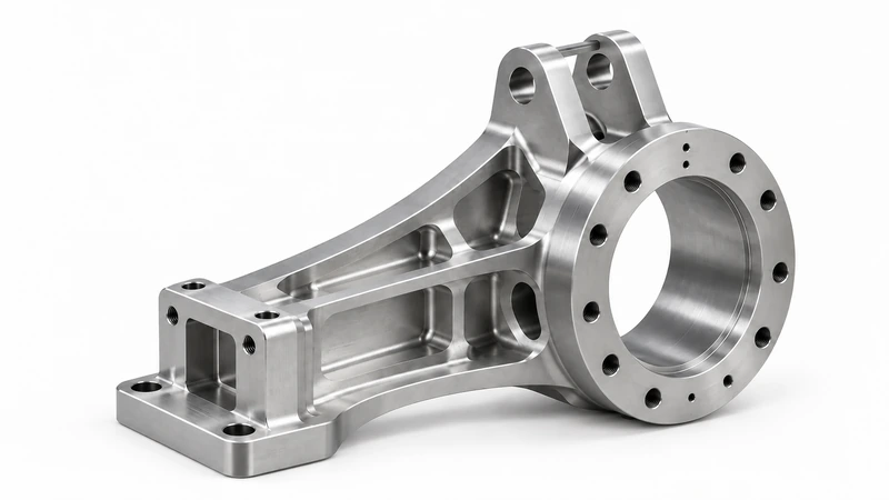
A 7075 aluminum robot joint bracket machined with 5-axis CNC to reduce datum transfer and keep critical multi-face features aligned for assembly.
This case involved a 7075 aluminum bracket for a robotic joint assembly. The part was compact, but its mounting holes, locating surfaces, mating interfaces, and weight-reduction features were spread across several faces. The challenge was not holding one feature to tolerance; it was keeping those features aligned to one another after machining from multiple directions.
With a conventional multi-setup process, every reorientation requires the part to be re-established. Each setup can be accurate on its own, yet small setup-to-setup errors can still shift the relationship between features on different faces. We therefore planned the process around the features that had to work together in assembly and kept related features in the same 5-axis setup wherever practical.
The purpose of 5-axis CNC machining was to reduce unnecessary re-clamping and datum transfer between related features. The machine provides the access needed to reach multiple faces, but the final result still depends on workholding, machining sequence, stock removal, and part stiffness.
The bracket also had weight-reduction pockets and locally thin walls. Removing too much stock early in the cycle would reduce stiffness and make the part more sensitive to clamping and residual-stress movement. We therefore left support and finish stock where needed, completed the critical interfaces first, and brought the thin sections and weight-reduction features to final size later in the process. Workholding was planned to avoid loading thin walls or blocking surfaces that still required finishing.
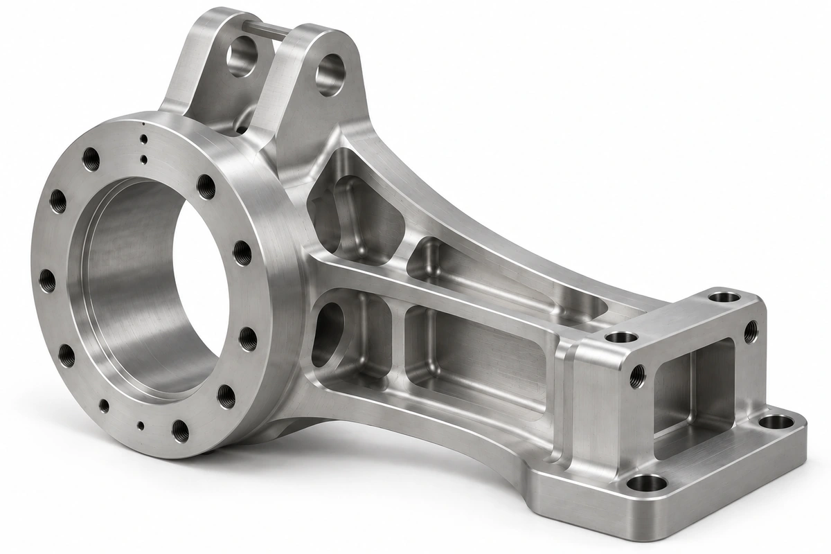
The starting material was 7075-T6. For similar parts machined from thick plate with heavy stock removal, 7075-T651 may be worth specifying because it is stretch stress-relieved and is commonly considered where post-machining dimensional stability matters. It is not the default for every 7075 CNC part; the temper should follow the drawing, stock form, and machining plan.
After machining, inspection focused on the same requirement that drove the process plan: whether the critical features still held the relationships defined on the drawing.
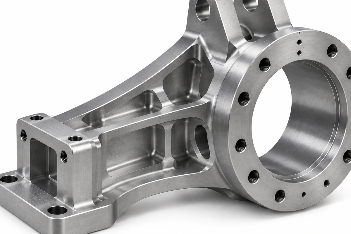
When the drawing uses GD&T, a CMM can establish the specified datum reference frame and verify how hole patterns, mounting faces, and mating interfaces relate to one another across the part. ASME Y14.5-2018 provides the framework for datum reference frames, position tolerances, and feature control frames used to define and verify those relationships.
A 0.03 mm position tolerance, for example, is meaningful only in the context of the controlled feature, the referenced datums, and the feature control frame. Flatness and surface-finish requirements are handled the same way: tight controls belong on functional surfaces that affect the bearing, actuator, or adjoining component, not on every surface by default.
The main benefit was not simply fewer setups. It was a process that kept related features under a more consistent datum scheme, managed stiffness as material was removed, and verified the finished part against the relationships that mattered in assembly.
For a robot joint bracket, that is the real measure of success: the part fits and functions in the joint assembly as intended.
If you are developing a robot joint bracket, actuator mount, bearing interface, or another CNC-machined component with critical features on multiple faces, send us your 2D drawing, 3D model, material requirements, expected quantity, and key assembly requirements.
Tongyong Industries can review the 5-axis machining route, workholding strategy, material condition, thin-wall machining sequence, and inspection plan for critical GD&T requirements.
Because assembly depends on the relationship between features, not just whether each feature passes on its own. Hole patterns and mounting surfaces can each measure within tolerance yet still shift relative to one another when they are machined in separate setups.
5-axis machining is most useful when critical holes, mounting faces, or interfaces are spread across several faces and need to stay aligned. It can reduce re-clamping and datum transfer, but geometry, tool access, tolerance, quantity, and cost still determine whether it is the right process.
When the drawing uses GD&T, a CMM can establish the specified datum reference frame and verify the relationship between critical hole patterns, mounting faces, and interfaces on different sides of the part.
If the drawing already specifies the temper, that requirement takes priority. For parts machined from thick plate with heavy stock removal, 7075-T651 may be worth specifying because it is stretch stress-relieved and can offer better post-machining dimensional stability. It is not the default for every 7075 part; the decision still depends on stock form, machining route, and drawing requirements.
Send your STEP, IGES, or DWG files along with your project requirements. Our engineering team will review your CNC milling requirements, assess manufacturing feasibility, and provide quotation and DFM feedback based on your project.
We use cookies to collect information about how you use this site. We use this information to make the website work as well as possible and improve our services.more details