Aluminum Encoder Knob CNC Machining Case Study
A custom aluminum encoder knob project focused on improving assembly stability, rotation performance, and anodized finish consistency for industrial control equipment.
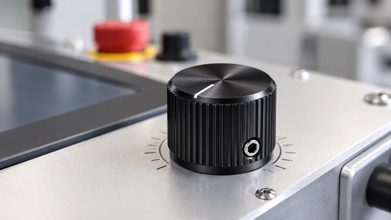
A custom aluminum encoder knob project focused on improving assembly stability, rotation performance, and anodized finish consistency for industrial control equipment.
How We Improved Rotation Stability Through Better Process Planning and Assembly Verification
Small components can create unexpected manufacturing challenges when they directly affect the user interaction experience. An aluminum encoder knob may appear simple, but its final performance depends on shaft fit, machining reference, fixing method, surface finishing, and assembly consistency.
This case study describes how we supported a manufacturer of industrial control equipment in improving the stability and consistency of a custom aluminum encoder knob from prototype validation to batch production.
| Item | Details |
|---|---|
| Product | Aluminum Encoder Knob |
| Application | Industrial Control Equipment |
| Material | 6061-T6 Aluminum |
| Size | Approx. Ø24 mm × 18 mm |
| Shaft Interface | Ø6 mm Encoder Shaft |
| Fixing Method | M3 Set Screw |
| Manufacturing Process | CNC Turning + Secondary Machining + Anodizing |
| Surface Finish | Black Anodizing |
| Production Stage | Prototype Validation → Batch Production |
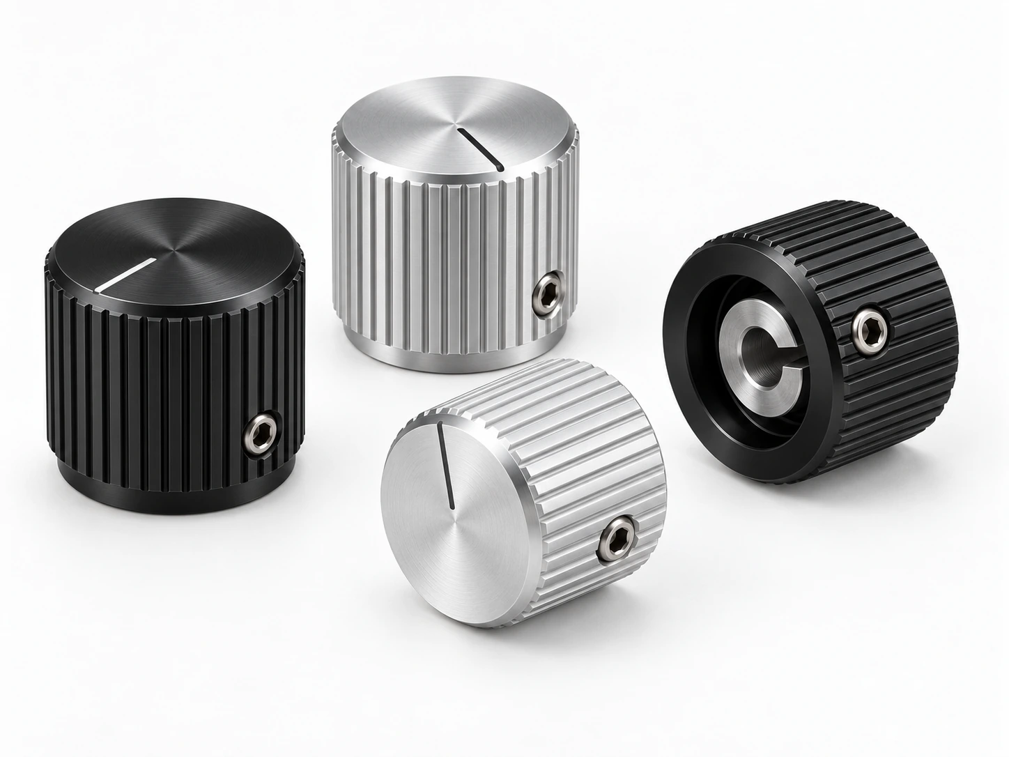
The first 50 prototype samples were successfully machined and assembled onto the encoder shafts. Individual dimensional checks showed no obvious issues, and the knobs could be installed normally.
However, during actual testing on the control panel, the customer noticed slight wobble during rotation on some samples.
The issue was not caused by a single dimension. The final rotation performance depended on the relationship between the shaft hole, outer diameter, machining reference, and the position of the set screw.
The initial samples showed approximately 0.08–0.12 mm runout after assembly.
For a rotating component like an encoder knob, the user does not see the shaft hole itself. What they see is the movement of the outer surface around the rotation axis.
The analysis showed that the critical features needed better control within the same machining reference system. The shaft hole, outer diameter, and end face worked together as a functional assembly rather than independent dimensions.
The set screw position was also considered because tightening force can influence the final position of the knob on the encoder shaft.
Instead of simply tightening every tolerance requirement, we focused on the features that directly affected the customer's final experience.
The machining sequence was adjusted so that the shaft hole, main outer diameter, and end face could be controlled under a more consistent machining reference whenever possible. This reduced the influence of secondary setups and improved the relationship between the rotating surface and the encoder shaft.
The inspection approach was also changed. Instead of checking only individual dimensions, the finished knob was verified under an assembled condition using a reference shaft to evaluate actual rotation performance.
Black anodizing improves appearance and durability, but functional areas such as shaft holes and fitting surfaces must be considered before finishing.
By reviewing machining and finishing requirements together, potential fit changes after anodizing could be reduced.
After process adjustments, the second-round samples achieved approximately 0.04 mm or better representative runout, and no noticeable wobble was observed during customer evaluation.
After prototype validation, the process was transferred into batch production of approximately 1,500 pieces.
| Inspection Focus | Purpose |
|---|---|
| Shaft hole dimension | Ensure encoder shaft fit |
| Runout after assembly | Confirm rotation stability |
| Set screw position | Maintain reliable fixing |
| Surface texture | Keep appearance consistency |
| Anodized finish | Maintain batch appearance quality |
For custom encoder knobs, adjustment knobs, and other shaft-mounted components, providing shaft specifications, fixing method, surface finish requirements, assembly conditions, and production quantity at the early design stage can significantly improve manufacturing results.
We typically need drawings or 3D models, encoder shaft specifications, fixing method, surface finish requirements, quantity, and assembly requirements.
6061 aluminum is commonly selected because it offers good machinability, strength, and anodizing performance.
Wobble control requires consideration of the shaft hole, outer diameter, machining reference, fixing method, and final assembly condition.
Common options include anodizing, bead blasting, brushing, polishing, and laser engraving.
Send your STEP, IGES, or DWG files along with your project requirements. Our engineering team will review your CNC milling requirements, assess manufacturing feasibility, and provide quotation and DFM feedback based on your project.
We use cookies to collect information about how you use this site. We use this information to make the website work as well as possible and improve our services.more details